a tube-based dice!
Why allways doing analog stuff with tubes?
Why not doing something digital?
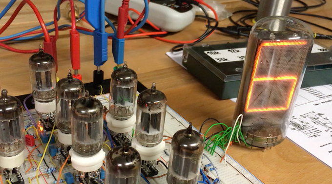
This was a very funny project with the goal to create a tube-based dice. It consists of 8x 5963 tubes, 2x INS-1 neonlamps, and a super large 7971 nixie tube (plus tons of resistors and diodes for specific RD logic circuits!)
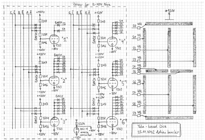
Here the schematics I developed:
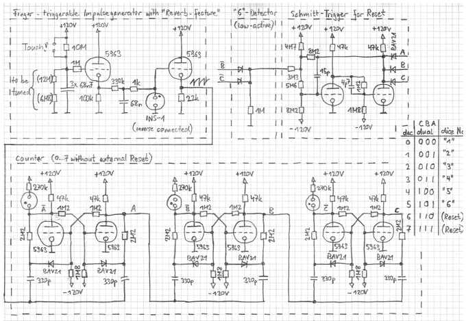
The basic idea is to use a neon glowlamp circuit to generate clock impulses for a digital 0-5 counter, combined with a fingertouch-trimmable supply for the glowlamp clock signal circuit.
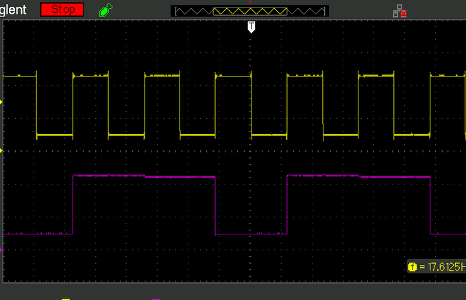
By default, this supply shall provide a voltage a bit below the absolute lowest voltage needed to get the glowlamp periodically ignited. When an open bridge is touched, some mircoamps flows across the bridge, increasing the voltage of the glowlamp supply. The glowlamp imediately starts to periodically ignite/recharge, with up to 30Hz or so. When the finger is removed, the glowlamp's supply voltage slowly decreases, and the clock frequency drops until the glowlamp completely stops to cycle.
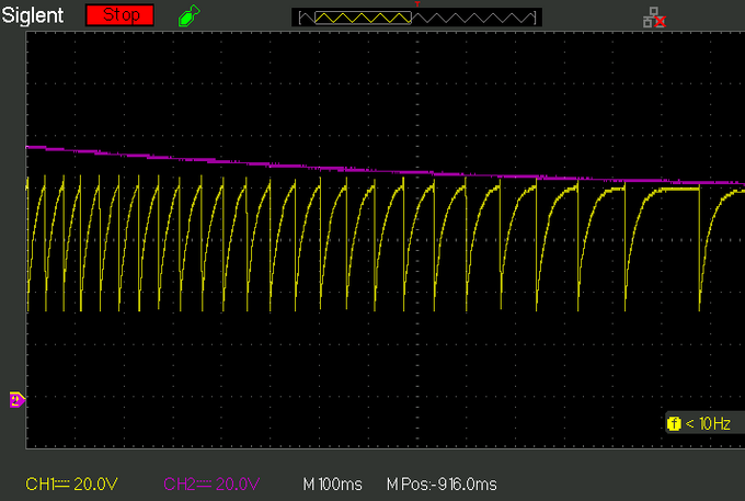
Note the scope traces, showing this circuit behaviour. In yellow the voltage across the glowlamp, and in voilet the glowlamp supply.
The following counter circuit is not my own development, but just an implementation of one of the various tube counter circuits presented in the web. Note that in addition, one needs to reset the counter to zero, when the seventh counter state appears. It turned out that a schmitt-trigger buffer is needed to store the reset impulse for a short time.
In the next scope graph, one can see output of the first f/2 flipflop in yellow, and the output of the third f/2 flipflop. Note their frequencies differ by a factor of 3, due to the RESET circuit.
But lets demonstrate how this fascinating tube-based dice performs!
Diese Seite teilen